Examples from dynamic simulation studies
Process Air Compressor Train
A compressor feeds several reactors
which may trip individually, often through a kind of explosion in the reactor.
The original control system was designed such that a reactor trip signal froze
the actual pressure at reactor trip as set point for the pressure limit
controller.
Analysis of the system in simulation
along with measured field data showed that the reactor trip signal was received
with a delay at a time when the compressor discharge pressure had already
increased drastically. It was further identified that the pressure increase was
mainly caused by reverse expansion from the reactor and only marginally by the
drop in process flow.
The control system was modified such
that the pressure spikes of the explosion do no longer impact the pressure
limit controller set point. The modified algorithm was tested and pre-tuned
along with the simulation model using the original controller software.
It was further noticed in simulation that a
change in the steam control system architecture allows avoid steam bypass
through letdown stations and such could safe MW in power.
The system is in industrial for 2
years now and the user reports significant improvements in the plant operation.
Process
Air Compressor Train
This process is similar to that
previously described, however number of reactors and process operation are
different. This system was modelled in a similar way.
Air Separation Compressor
A set of large motor driven axial
flow compressors, each equipped with 2 intercoolers, feeds air separation units
in a remote area without connection to the public grid. The motor driving power
is generated in gas turbine generator sets. On any gas turbine failure, one or
several compressors are forced into an emergency stop which resulted in a
compressor surge, as the speed drop was faster than the unloading of the
compressor through the 1 second to open blow-off valves.
The aim of the simulation study was
to investigate by which measures these rundown surges can be avoided.
A large set of high speed recorded
data were available from these events. These allowed verify the simulation
model before the actual simulation runs were made. It was identified that the
reverse flow through any of the stage groups has a tremendous impact on the
simulation results. Without reverse flow simulation during surge, it appeared
that only the final (centrifugal) stage is affected by surge. Including the
reverse flow resulted in very good compliance between model and reality. In
simulation, surge of the first compressor stage started 430 milliseconds after
the motor stop signal, in reality 846 milliseconds were measured.
The simulation showed that rundown
surge can be avoided if the blow-off valves are fully open after 500
milliseconds and the discharge check valve is closed after 300 to 350 milliseconds.
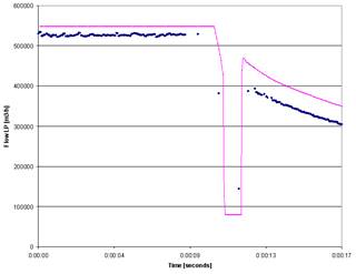
Track of first stage and third stage
flow (measured shown dark blue, simulated shown magenta)
Gas Gathering Compressor
A gas gathering station consists of
three compressors in parallel. Gas from 4 trunk lines feed the compressor station.
The compressed gas leaves the station through 4 other trunk lines. The main aim
of the station control system is beside maintaining the inlet and outlet
pressure to have the maintain the flow ratio of the incoming trunk lines on the
outgoing lines. To meet this requirement, flow controller are provided in each
incoming and outgoing trunk line. It was envisaged that the incoming flow on
each line determines the set point for the outgoing flow.
The simulation team insisted in
having incoming and outgoing trunk lines included into the model despite that
these trunk lines were outside the battery limits of the engineering company.
These lines needed to be included to identify any counteraction between these
trunk lines and the compressor station.
During the simulation it was
identified that the basic control concept was not workable. The entire concept
was modified and then verified during the simulation study.
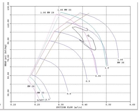
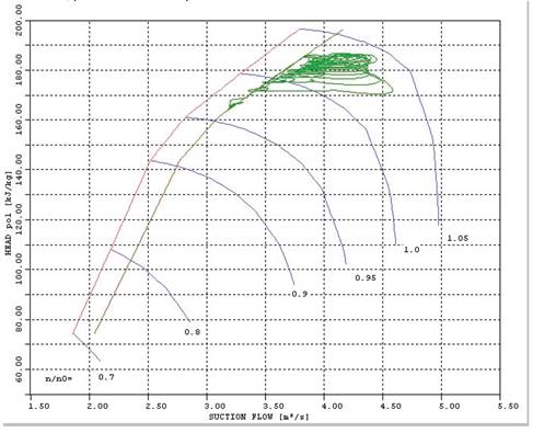
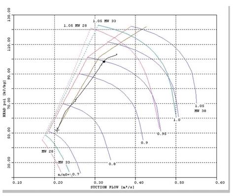
Tank Vapour Extraction Compressor
A compressor system with two stage
groups is used to compress evaporated gas from a tank system and separate most
of the hydrocarbons into liquid form. Thus, the molecular weight of the gas
entering the compressor is much higher than the molecular weight of the gas
leaving the aftercooler. The opening of the compressor anti-surge valve changes
the molecular weight of the HP compressor inlet instantaneously. This results
in an increase in compression head which moves the operating point towards the
direction of the control line. Continuous oscillations of the recycle valve,
followed by oscillations of the molecular weight were seen in the simulation. Advanced
control strategies were developed to cope with this operation.
Due to changes between summer and
winter and property of the gas, the molecular weight can vary in wide ranges in
addition to above dynamic molecular weight changes.
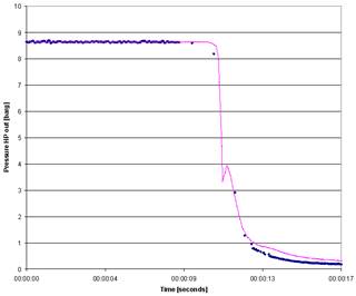
System Response on recycle valve
opening
Control response of original control
system
Control response of improved control
system
Anti-Surge Control Improvement
A company which operates a large
fleet of compressor trains has developed their own anti-surge control algorithm
which can run on the plant PLC system. First field experience showed that a
guide vane movement of less than 1% per second can drive the compressor almost
into surge despite the fact that the controller was tuned such critical that
continuous oscillations could be initiated by any larger process upset.
It was decided to let Blotenberg
Turboservice develop an improved algorithm and test it along with a dynamic
simulation model. The model was connected through a Digital to analogue and
analogue to digital converter with the original control system and the entire
system tested online in real time.
Multi-stage-group offshore Compressors in parallel operation
A gas compression system consists of
three compressors, each having three stage groups in parallel. This matrix of 9
compressor stages is controlled by 27 control loops, amongst them 9 anti-surge
controller, 6 pressure controller and 9 load sharing controller. A dynamic
simulation study was done prior to the installation which proved that the
system can be operated under stable conditions in full load and part load
operation.
During commissioning, it was not
possible to operate the trains in part load. The anti-surge loops interacted
such that stable operation was impossible.
Recorded high speed field data gave
the impression that the anti-surge control valves include a hysteresis. This
hysteresis was added to the simulation model and the simulation showed the same
result as that which was reported from the site.
After the valve vendor has fixed the
valve, the system was commissioned successfully and operated for many years.
FCC Expander Generator Driver
An expander/generator set recovers
energy from a refinery process by expanding offgas with 3.7 bar abs and 760 °C
to atmosphere and recover 6 MW electric power. To protect the train from
overspeeding on electric load shedding, the expander inlet valves need to close
in 0.6 seconds. To avoid impact on the process, expander bypass valves need to
open in a controlled mode and ensure that the system pressure does not change
by more than 30 mbar.
The system was investigated in a
dynamic simulation study. An advanced control algorithm was developed, tested
and pretuned. Using these pretuned parameters, the installed control system
showed a pressure change of 28 mbar at full flow trip. Further tuning could
reduce the changes to 11 mbar.
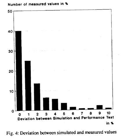
Simulation of a Gas Turbine
A twin shaft industrial gas turbine
was simulated over the entire operation envelope. The simulation runs were
compared with test bed measurements. 140 different points were available. 65 %
of all points did not deviate by more than 2 %, 90 % did not deviate by more
than 5 % and highest devistion of 10 % was the GT efficiency at 0.1 % of GT
load.